I’m not sure where you are, but US libraries 3D print STL files for free. I.e., take the STL file to the library and they’ll make this for you free of charge. Google your local libraries and search their sites for 3D printing for specifics and limitations.
3 Likes
Hello All.
I tried to access the spreadsheet I made that requires aim angles and bracket thickness (defaults to 8mm) and then generates the STL output to print the DogLeg Standup bracket, but it didn’t work so here is a fresh link. DogLeg Standup to STL
Victor.
4 Likes
Hello @BillyCroan.
Below is the results of making a Full Section Window-Mounted V3 Tube Glare Shield Camera Holder.
The first picture below is the printed results.

The next two pictures show it mounted on a window with a working V 3 with its base attached. This was a temporary mount, that is why so little tape is used.

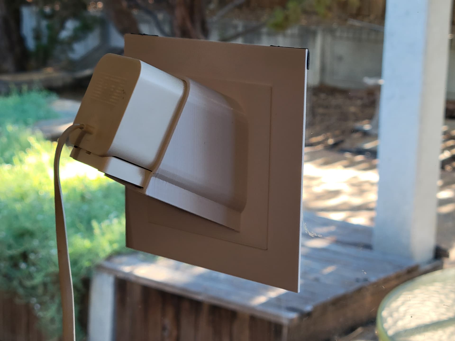
The picture below shows the field-of-view restriction caused by the shield’s geometry for a 25° Rt aim angle. A 20° Rt angle would have much less restriction. Often the FOV restriction is hiding another restriction, the side frame of the window. In other words, if the camera were free of tube and shield geometry, the window’s side frame would block part of the view.

This last picture is a copy, for viewing, of the PDF file with detailed section dimensions.

Below is a link to the actual PDF with all of the needed V3 section dimensions.
Full Section V3 with Glare Guard.PDF
For detailed instructions in a word document format, check this link.
Create Your Own Custom Window Mount Sq Tube Glare Shield Drawing This document explains all of the steps needed to go from a scaled drawing of the camera’s section that includes fit-up allowances, the location of positioning axes, calculating Working Length, positive and negative extrusions, unions, order of rotations, another union, two subtractions, and finally checking the finished product. Then the part is exported to an STL file.
Till later.
Victor.
1 Like
Could you make the tube part widen as it gets closer to the window, kinda like a dome? So you don’t see the plastic in the camera view.
1 Like
I am working on two approaches that will solve that issue. But it won’t be printed. It will be folded. Stay tuned.
Victor.
2 Likes
Hello IEatBeans.
To eliminate F.O.V restrictions for a 45 deg Rt aim, the shield would need to be about 9" wide and at a very low slope. A 3D print ould be very problematic.
Victor.
Hello @BillyCroan @IEatBeans and Others.
It has been a while since we last communicated through the Wyze Forum. Some of the earlier discussions concerned the camera’s cone of vision. I sent out my procedures for making STL files for square tube and full-section angled window-mounted glare shields. Since then I have been working with flared shields. Since the camera’s field of view is a rectangle, I began working with a square flare instead of a cone flare. I chose the square pyramid flare over a rectangular pyramid for its ease of mating geometry with a baseless V3 camera.
While working with a square pyramid flare, I was able to eliminate the lengthy calculation for the ‘working distance’. Only simple triangular calculations are needed. Soon I will be posting about the pyramid-flared glare shields. If you are interested in a preview of what an 80° 15°Rt 15°Dn pyramid glare shield looks like I will send you an STL file for it. The 80° in the file above refers to the apex angle of the pyramid. I find that 80° and 90° are practical and any larger ones are impractical.
et me know if you are interested.
Victor.
1 Like